


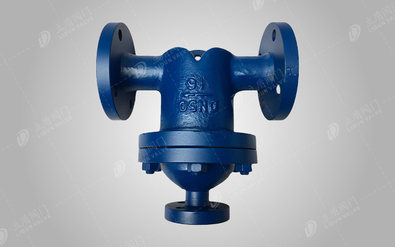
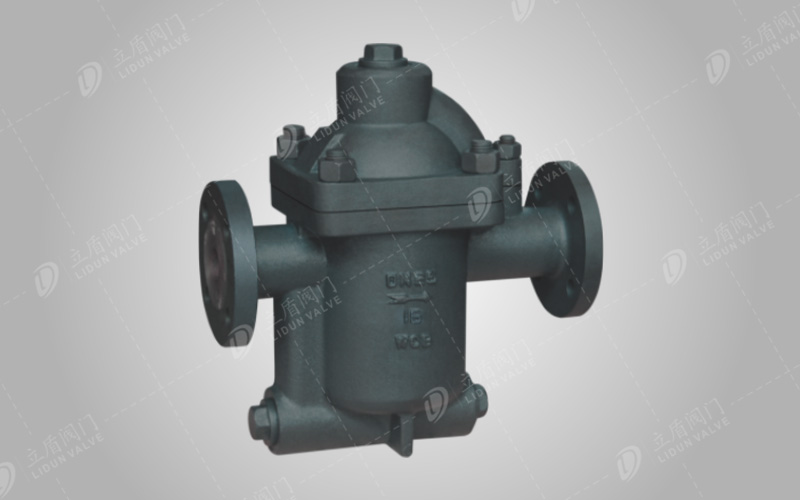
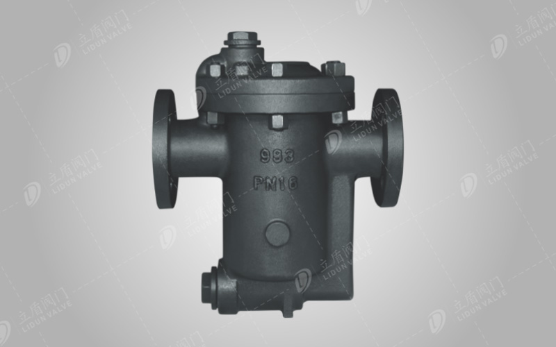
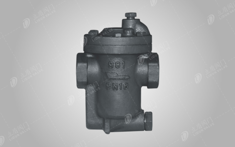
Product model: UFS
Nominal diameter: DN20~300mm
Nominal pressure: PN1.6~2.5Mpa
Working pressure: PN1.6~2.5Mpa
Working temperature: 425°C
Product overview
The steam separator uses the pattern in the body and the principle of steam and water flow to produce different flow directions, and the medium flow direction is sharply converted to separate the steam from the suspended water droplets contained in the steam, which improves the dryness of the steam (the dryness can reach 98%) and ensures the smooth operation of production.
Product features
1. Improve the dryness of steam and send it to the steam equipment to improve the thermal efficiency of the equipment.
2. Prevent water hammer, and the separated condensate is discharged through the trap below.
3. UFS type steam separator is also suitable for the separation of various gases and liquids.
Material of main parts
|
Part Name |
Material |
|
Valve body, bonnet |
cast steel |
|
filter cover |
stainless steel |
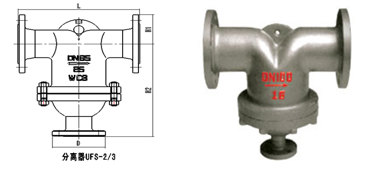
External Connection Dimensions
|
product
|
Nominal diameter(mm) |
connection method |
use (Mpa) |
allowable temperature(℃) TMP |
Dimensions(mm) |
|||
|
L |
H1 |
H2 |
D |
|||||
|
UFS1 |
50 |
flange |
0.01-2.5 |
350 |
270 |
80 |
250 |
25 flange |
|
65 |
310 |
90 |
275 |
|||||
|
UFS2 |
80 |
flange |
0.01-2.5 |
350 |
400 |
107 |
320 |
25 flange |
|
125 |
108 |
370 |
||||||
|
UFS3 |
150 |
flange |
0.01-2.5 |
350 |
450 |
140 |
410 |
50 flange |
|
200 |
168 |
435 |
||||||
|
UFS4 |
250 |
flange |
0.01-2.5 |
350 |
550 |
203 |
517 |
50 flange |
|
300 |
600 |
230 |
570 |
|||||
|
0.01-4.0 |
600 |
257 |
585 |
|||||
|
UFS5 |
350 |
flange |
0.01-2.5 |
350 |
700 |
275 |
650 |
flange |
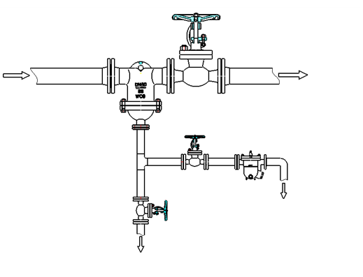
Precautions for installation and use
1. Before installation, the pipeline must be purged with pressure gas to remove dirt and sundries.
2. The separator should be installed at the lower position of the steam pipeline. It is recommended to install a stop valve before and after the separator.
3. Installation direction: The arrow on the valve body points to the same direction as the fluid in the pipeline (the arrow on the valve body points to the fluid outlet port).
4. A drain valve should be installed at the lower part of the steam-water separator, and the drain valve should be selected according to the displacement and working conditions.
5. In order to prevent the steam-water separator and the lower steam trap from malfunctioning due to dirt blockage, it is recommended to install a filter in front of the steam trap and clean it regularly to ensure the normal operation of the equipment.
Add: No. 175, Lane 250, Fangde Road, Jiading District, Shanghai
Tel: +86-21-51863336
Fax: +86-21-34677003
E-mail: shldv@139.com
Web: Http://m.lisagf.com
Fujian plant site:2233 Maosheng Road, Nan 'an City, Fujian Province
Factory telephone:+86-21-31007333

 Shanghai Public Network Anbei: 31011402004337Sitemap
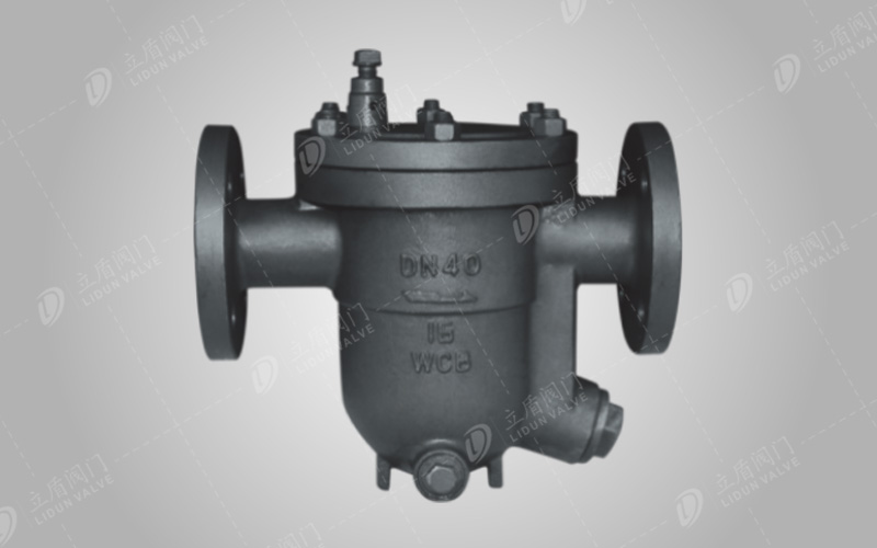
 Home
Home Products
 Application
 Tel
Tel